Share this article:
Solis Technical Guide: Smart Meter Phase Rotation and CT Polarity Verification
Proper installation and commissioning of Smart Meters and Current Transformers (CTs) are critical for the correct and stable operation of Solis systems. Whether installing a Solis Export Power Manager (EPM) or a Solis Energy Storage Hybrid Inverter, system performance depends entirely on meter measurement accuracy.
Errors in CT polarity or phase rotation lead to operational issues—ranging from unexpected battery charge/discharge behavior to system trips or over-generation during export-limited operation.
Physical CT Placement Location (Point of Common Coupling)
Current Transformers (CTs) must always be installed on the main incoming utility service cable (Point of Common Coupling / PCC).
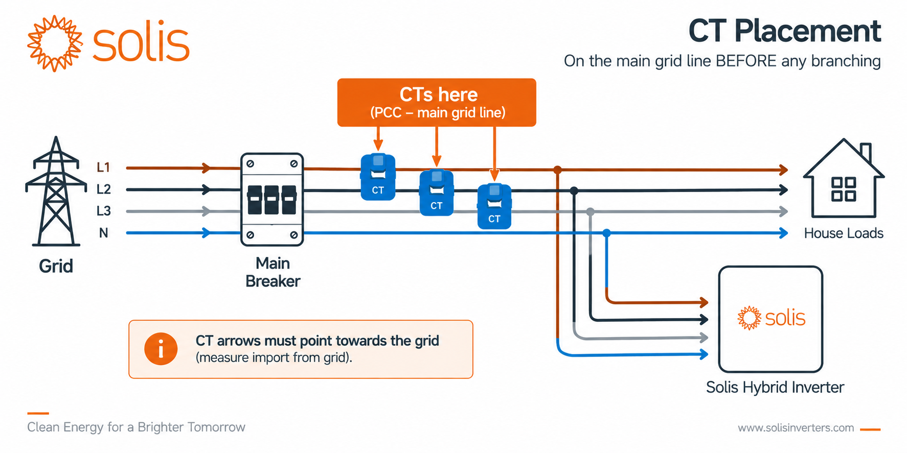
Golden Placement Rule: CTs must be clamped onto the incoming lines BEFORE any electrical branching—directly after the main service switch or utility meter, but before the distribution busbars/breakers feeding site loads and the inverter. Only in this position can the meter register the true net energy balance.
Understanding Solis Real Power Logic
Before conducting diagnostics, it is essential to understand how Solis meters and inverters interpret power flow direction:
Positive Real Power (+kW) = EXPORT
PV generation or battery discharge exceeds local site demand. Excess power flows into the grid.
Negative Real Power (-kW) = IMPORT
Site demand or battery charging exceeds PV output. Power is drawn from the grid.
Core Troubleshooting Rule: Always monitor Active Power in kW on a per-phase basis (L1, L2, L3). Do not rely on kWh (accumulated energy), kVA (apparent power), or kvar (reactive power), as these metrics do not indicate power directional sign.
Step 1: Phase Rotation and Phase Matching Verification
Important Note: Diagnostics must always begin with Phase Rotation verification! If a voltage input (V1) is paired with a CT from a different phase (CT2), the meter will calculate incorrect active power values and misrepresent the power direction sign (+/-). Checking CT polarity before confirming correct phase matching is ineffective.
What is Phase Rotation Error?
Phase rotation error occurs when a voltage reference input for Phase 1 (V1) is paired with a Current Transformer from Phase 2 (CT2) or Phase 3 (CT3). This introduces a 120° or 240° phase angle shift, causing the meter to display incorrect Power Factor (cos φ) and active power readings.
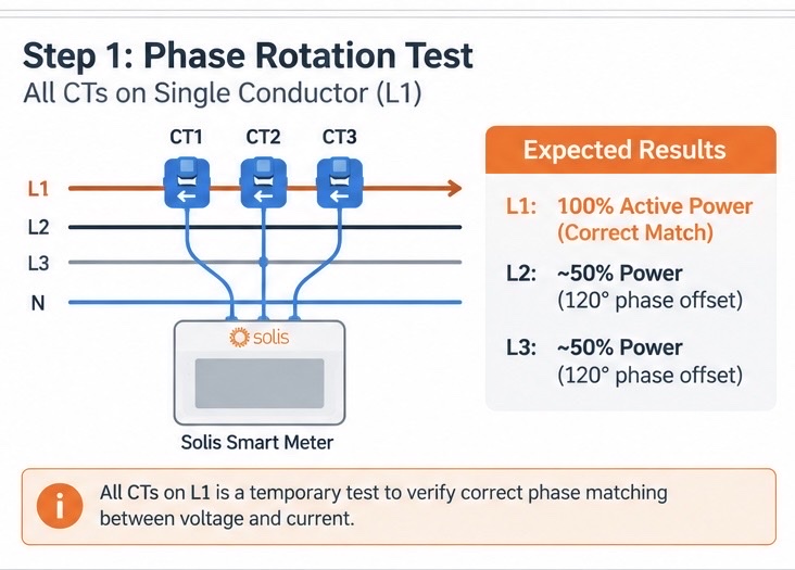
The "All CTs on One Phase" Isolation Test
To quickly identify phase mismatch:
Clamp All CTs to a Single Conductor: Temporarily attach CT1, CT2, and CT3 to the same physical phase conductor (e.g., Phase L1).
Establish Load: Ensure active site consumption or export.
Requirement: The current on the phase must be at least 5A (approx. 1 kW active load). Lower current levels may lead to inconclusive readings due to electrical noise.
Analyze Meter Display:
Matching Phase: Only the voltage channel corresponding to the selected conductor (L1) will display true high active power and a correct cos φ.
Mismatched Phases: Due to the 120° phase shift (cos 120° = -0.5), the other two channels will read approximately 50% lower active power than the actual value (or show negative power).
Correction: Keep CT1 on L1, and move the remaining CTs to their respective conductors until each voltage-current channel pair matches correctly.
Step 2: CT Polarity Verification
Once phase rotation is confirmed, verify the physical orientation and polarity of the CTs. A reversed CT causes the meter to misread import as export and vice versa.
System Impact:
EPM Systems (Export Limitation): If export is limited (e.g., to 100 kW) and CT polarity is reversed, importing 100 kW will be misread as exporting 100 kW. The EPM controller will ramp up inverter output further, causing system trips or grid compliance violations.
Hybrid Systems with Energy Storage: Inverter logic becomes corrupted. The battery may remain idle or cycle unexpectedly between charging and discharging.
Step-by-Step Polarity Check:
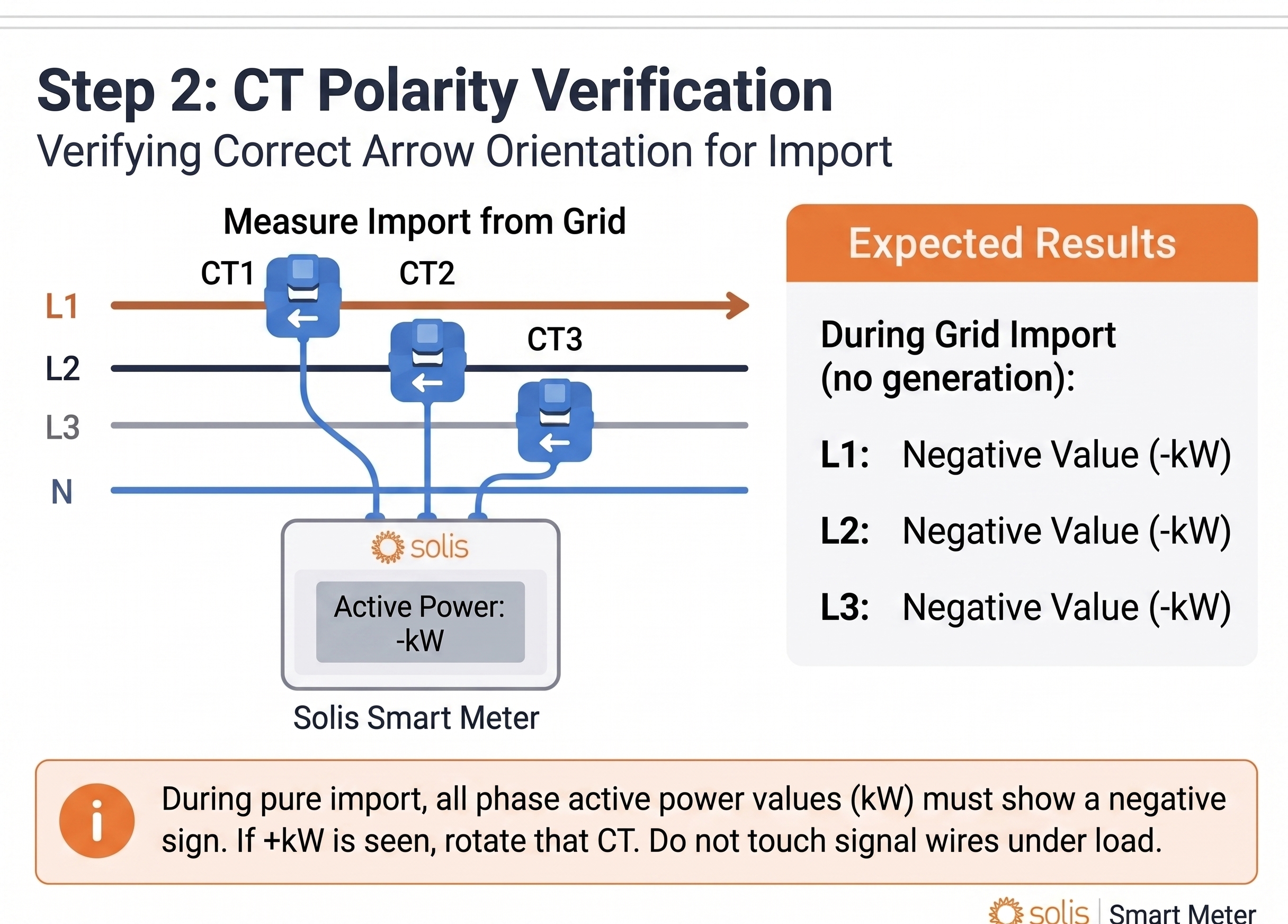
Establish a Known "Pure Import" State:
Ensure power is flowing exclusively from the grid to the load:
Standard PV Systems: Turn off PV inverters and turn on heavy site loads (e.g., water heaters).
Hybrid Systems: Force battery charging from the grid (Forced Grid Charge).
Check Per-Phase kW Readings:
Normal Condition: All phases display negative active power (e.g., L1 = -1.2 kW, L2 = -1.1 kW, L3 = -1.4 kW).
Polarity Error: If L1 and L2 display negative values while L3 shows a positive value (+1.2 kW), CT3 is reversed.
How to Correct CT Polarity:
Physical CT Rotation (Recommended & Safest Method): Unclip CT3 and rotate it 180° directly on the power cable. The reading will immediately switch from +1.2 kW to -1.2 kW.
Important Note on Manual Diagrams (Arrow & Wiring Markings):
Always verify the wiring diagram for the specific meter model in the manual. On certain Solis setup diagrams, the CT arrow is designated to point toward the grid (CT Arrow -> Grid), with secondary signal leads color-coded accordingly (e.g., Black / White for S1/S2).
Golden Rule for Field Testing: Regardless of physical arrow labeling on the CT shell, during a forced pure import state (zero PV generation and no battery discharge), the meter must display negative active power (-kW) across all phases. If +kW is shown, reversing the CT orientation is required.
Safety Warning: Do not disconnect secondary CT signal wires (S1/S2) while the primary conductor is under load! Opening a secondary CT circuit under load generates high voltage that can damage the transformer or meter terminal block. Always flip the CT orientation directly on the primary cable.
Inverter Phase Alignment for Unbalanced Injection
In hybrid systems operating in Unbalanced Mode, after correcting phase rotation on the meter, verify phase sequence alignment at the inverter Grid Port terminals.
Example: An installer wired both the meter and inverter as L3, L2, L1 based on cable colors. Phase rotation on the meter was then corrected to L1, L2, L3.
The Problem: If the inverter Grid Port remains wired as L3, L2, L1, a phase mismatch occurs. In Unbalanced Injection mode, when the meter requests 3 kW output on Phase L1, the inverter will output that power onto its physical Phase L3, causing control logic failure.
On-Site Commissioning Checklist
Checkpoint | Target State | Action if Faulty |
|---|---|---|
CT Installation Location | Main incoming cable BEFORE any branch to loads or inverter | Move CTs to main incoming line (Point of Common Coupling). |
Voltage Sequence | V1 -> L1, V2 -> L2, V3 -> L3 | Rewire voltage sensing terminals to match supply phases. |
CT Pairing | CT1 -> L1, CT2 -> L2, CT3 -> L3 | Run the single-conductor isolation test (current ≥ 5A). |
CT Polarity & Direction | Meter displays -kW across all phases during pure import | Rotate CT physical orientation by 180° on cable. Verify diagram compliance (e.g., Black/White leads or P1 -> P2). |
Inverter Sequence | Meter Phase Order = Inverter Grid Port Phase Order | Verify AC cable connection sequence at inverter grid terminals. |
Power Direction Sign | All phases show -kW during forced grid import | Correct CT orientation on any phase showing +kW. |