Share this article:
Solis Installation Guide
By Mindaugas Legeckas, Technical Department – Update 09/2026
This comprehensive installation guide is designed to support installers through every stage of deploying Solis inverters, from PV cabling and electrical connections to full system configuration. It covers key setup options, inverter commissioning, battery integration, and parallel operation to ensure safe and optimal performance. Whether working on residential or commercial systems, installers will find clear, practical guidance throughout.
The complete guide is available to download at the bottom of this article in PDF format.
This guide is intended exclusively for certified installers and qualified technical personnel; end customers experiencing issues with their SOLIS installations should contact their original installer, as technical support and on-site service are handled directly through the installing professional.

Table of Content:
- Installation Preparation
- Grounding system inspection
- Electrical distribution board assessment
- Installation Diagrams
- Cable connection
- Grounding
- Installation requirements
- PV Cabling
- Installation Inspection
- Most Popular Products
- S6-EH1P(3-8)K-L-PLUS CT
- S6-EH3P(8-18)K02-NV-YD-L CT
- S6-EH3P(12-20)K-H
- S6-EH3P(12-20)K-H Ports
- Paralleling
- Heat Pump Connection
- Generator Connection
- S6-EH3P(12-20)K-H Implementation Diagrams
- S6-EH3P(12-20)K-H – Dual Meter Settings
- Energy Storage Modes
- S6-EH3P(80-125)K10-NV-YD-H
- Smart Port
- S1-109EC3P50K04-NV-YD-H
- Solis EverCore
- Solis Storage Batteries
- Solis EMS
- RMA Process

You are electrical engineers!
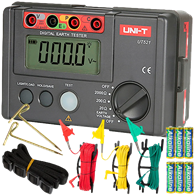
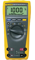
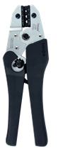
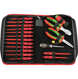
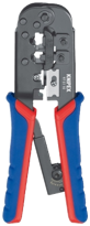
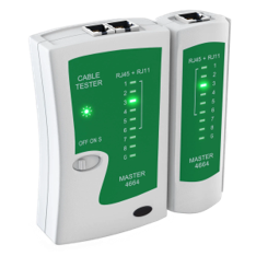
Tools you will need:

Preparation
General Rules for the Installation of Electrical Equipment: What Are They and Why Are They Important?
The General Rules for the Installation of Electrical Equipment are a set of regulatory requirements governing the safe and proper design, installation, and operation of electrical installations. Their purpose is to protect people, ensure the reliable operation of electrical equipment, and reduce the risk of fire, electric shock, and equipment damage.
Compliance with applicable mandatory requirements is required by law. Failure to comply may increase safety risks and may result in legal or regulatory consequences.
Where the applicable rules include recommendations or guidance rather than mandatory requirements, these should also be carefully considered. Such recommendations are generally based on established engineering practices and are intended to improve the safety, reliability, and overall quality of the installation.
Preparation and Evaluation
Grounding system inspection
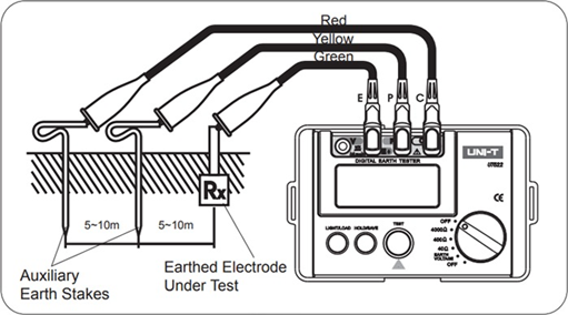
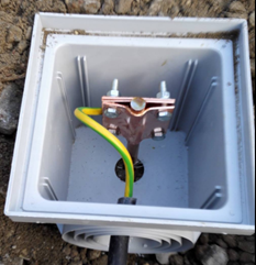
Not more than 10 OHMS
Electrical distribution board assessment
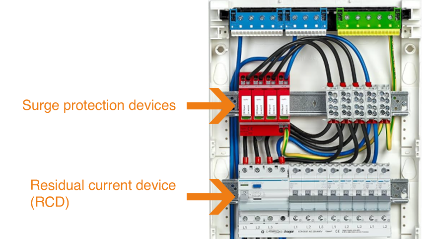
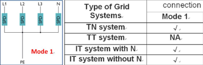
Grid overvoltages may generate transient surges that propagate through the supply lines. Large inrush currents or short-circuit conditions can produce extremely high currents within milliseconds, potentially resulting in transient overvoltages.

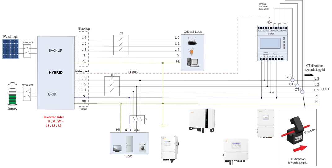
Diagram (Original)
Diagram
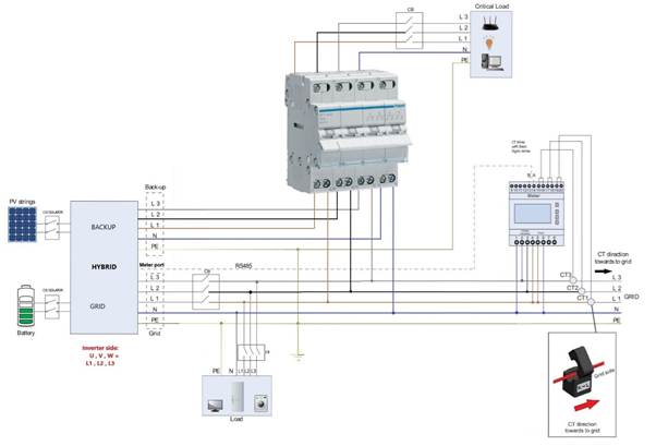
(With Manual Switch)
Visual Diagram
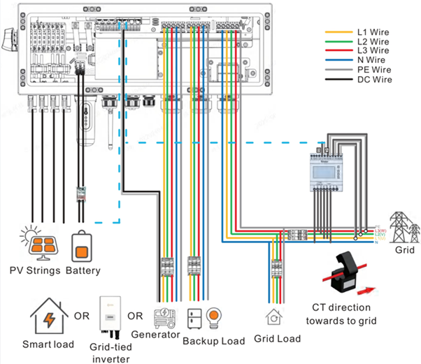
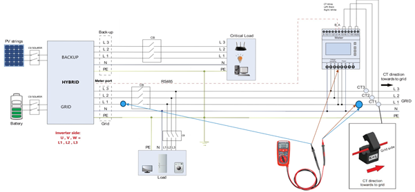
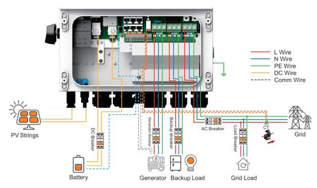
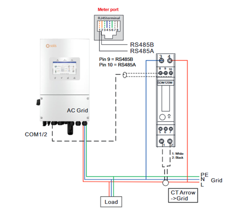
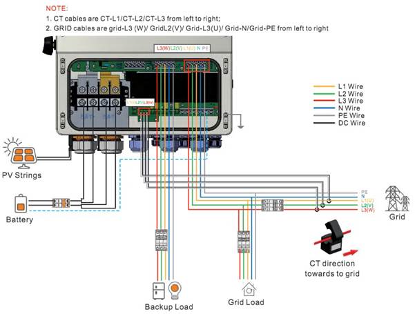
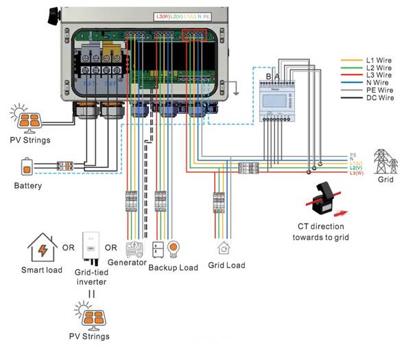
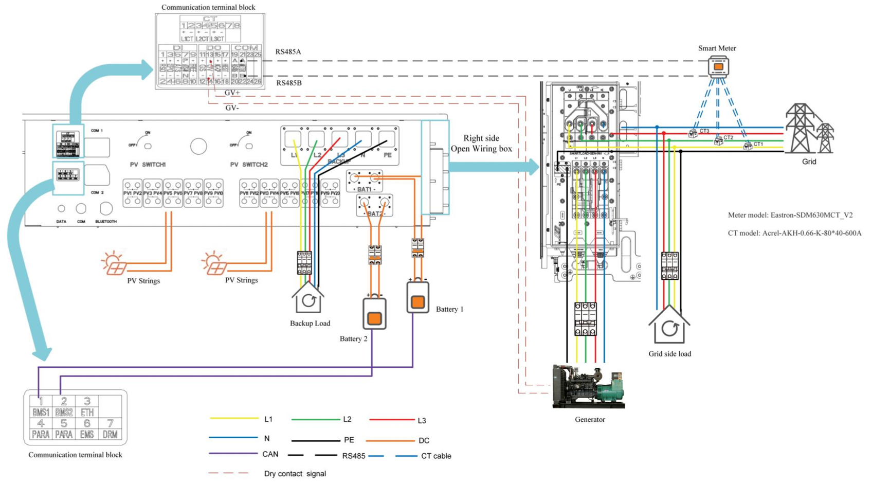
This diagram illustrates the connection of a hybrid inverter to the electrical grid, loads, battery, and photovoltaic (PV) system. The energy meter and current transformer (CT) clamps are installed on the grid side. The CT clamps must be oriented toward the grid to ensure accurate measurement of energy import and export.
The diagram supports the separation of Grid Loads and Backup Loads. It also allows for the connection of additional equipment, such as a generator, smart load, or grid-tied inverter.
All phases (L1, L2, and L3), neutral (N), and protective earth (PE) must be connected to their corresponding terminals. Correct wiring and terminal connections are essential to ensure accurate energy monitoring and proper inverter operation.

Installation
Cable connections:
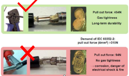
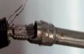

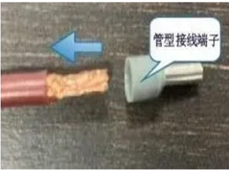
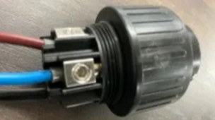
It is recommended to use tubular cable ferrules on stranded conductors to prevent strand spreading and ensure a secure, reliable, and high-quality connection between the AC conductors and the AC terminals.
Grounding:
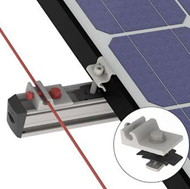
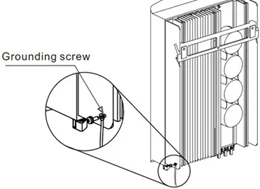
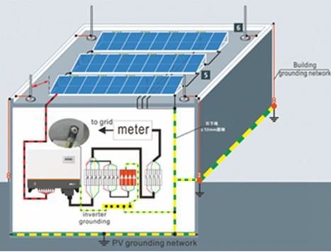
Proper protective earthing (PE) is essential not only for electrical safety but also for stable and reliable inverter operation. An effective earthing system helps reduce electrical noise and transient voltage disturbances and can improve measurement accuracy, particularly when using CT clamps, energy meters, and communication systems.
Improper or disconnected PE connections may result in communication errors, unstable operation, false alarms, or, in some cases, inverter shutdowns.
Installation requirements:
1: The installation location must meet the following requirements (see manual for each model – Example S6-EH3P(12-20)K-H
:
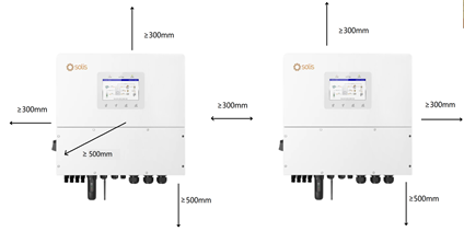
Taking into account the operational, installation, and maintenance requirements, the installation may be adapted to the actual site conditions. The recommended airflow configuration is air intake from the bottom and air outlet from the top.
2: Load-bearing surface:


Made of non-combustible materials.
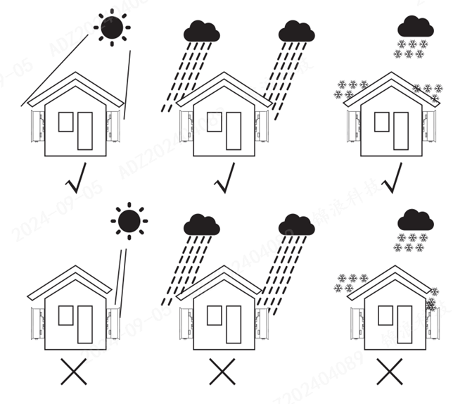
3. Installation environmental conditions:

4. Recommended installation locations:
PV Cabling
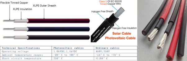
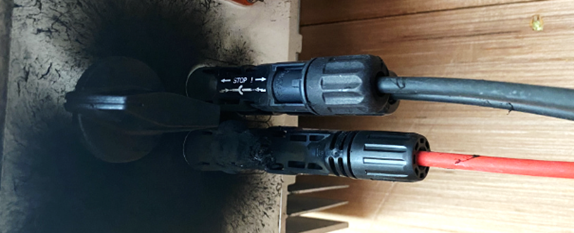
The use of high-quality PV cables is essential for safe and reliable long-term system operation. PV cables designed for the intended application provide resistance to UV radiation, temperature fluctuations, and moisture, helping to minimize power losses and reduce the risk of overheating, insulation degradation, and cable failure.

Installation Inspection
Supports unbalanced output mode
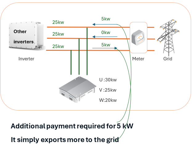

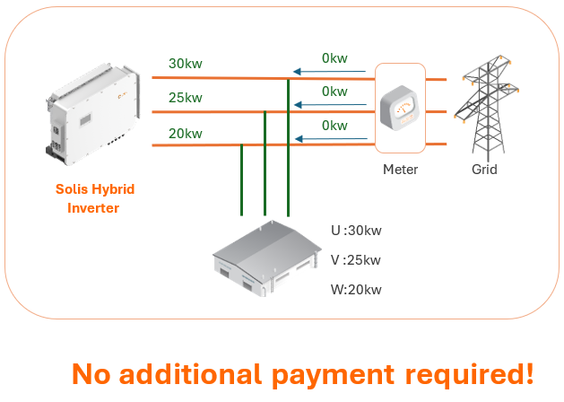

Installation Inspection (Basic)
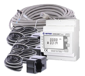
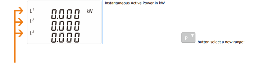
Phase Sequence and CT Clamp Verification
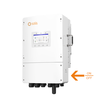
Before checking the phase sequence, switch off the inverter through the menu (Inverter → OFF) and switch off the battery, if it is connected to the hybrid inverter.
At this stage, the expected meter readings should be negative, indicating that energy is flowing from the grid toward the household loads. If the CT clamps are installed correctly, verify that each CT clamp corresponds to the correct phase (L1, L2, and L3) and that the measured values are consistent with the actual load on each phase.
After completing the verification, switch on only the battery and enable the Unbalanced Output function. Check the meter LCD display. The readings should be zero or close to zero.
This verification is important because incorrect phase or CT connections may cause the inverter to operate incorrectly, potentially resulting in unnecessary battery discharge while electricity is simultaneously being imported from the grid.
Installation Inspection (Advanced)

Customer Service Recommendations

- Solis Technical Support is primarily intended to assist installers with technical issues related to inverter installation, configuration, commissioning, and fault diagnosis.
- As technical support is provided to installers on a priority basis, installers are expected to manage routine customer inquiries and provide customers with guidance on standard inverter configuration and operation. End customers should generally be supported directly by the installer rather than being referred to Solis Technical Support for routine assistance.
- Solis Technical Support does not provide training to end customers on inverter configuration or operation. Its primary role is to assist installers with fault diagnosis, troubleshooting, and other technical issues that require specialist support.
- Directing end customers to Solis Technical Support for routine inquiries may increase response times and could delay assistance to installers who require technical support for active installations or faults.
- Therefore, installers should handle customer inquiries directly and contact Solis Technical Support when specialist assistance is required for fault diagnosis, troubleshooting, or other technical issues that cannot be resolved through the available installation and product documentation.

Popular Products
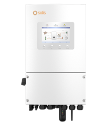
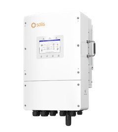
3-8K-L Plus 8-18K-L
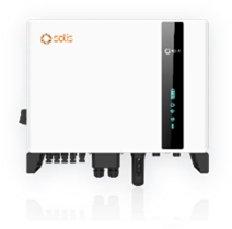
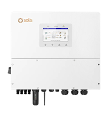
3-10K-H 12-20K-H
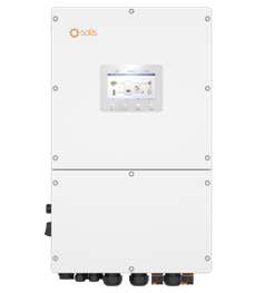
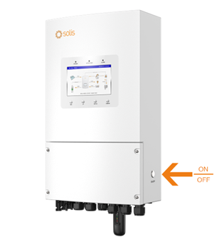
30-60K-H
S6-EH1P(3-8)K-L-PLUS CT
 ç
ç
S6-EH1P(3-8)K-L-PLUS METER
S6-EH3P(8-18)K02-NV-YD-L CT
S6-EH3P(8-18)K02-NV-YD-L METER

S6-EH3P(12-20)K-H
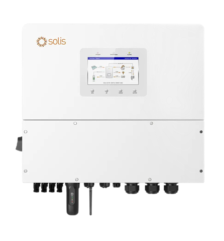
4 MPPT / 4 Inputs - 20A current per string
50A - Maximum charge/discharge
160% long-term PV input capacity - 40 kW PV array size / 32 kW usable PV input
Smart Port – multifunctional - Two generator connection types: AC coupling, Smart Load
Remote monitoring - For clear understanding and analysis
Automatic UPS switching - <10ms
Parallel system - On-grid or off-grid, max. 120 kW in parallel
200% overload capacity for 10s - Temporary overload
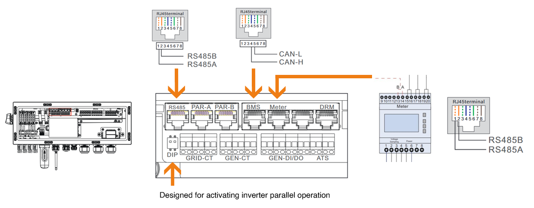
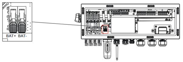
S6-EH3P(12-20)K-H Ports

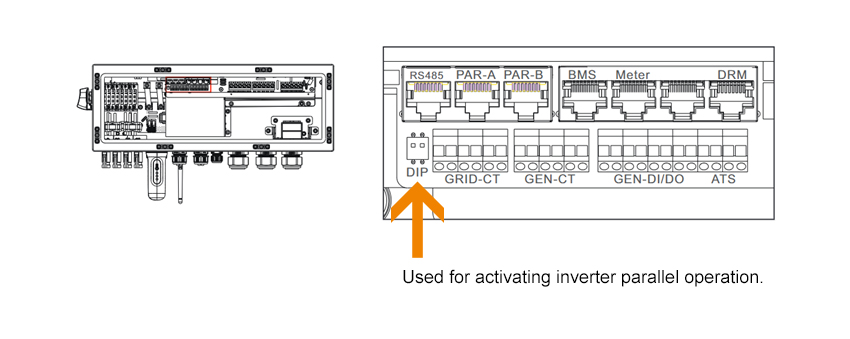
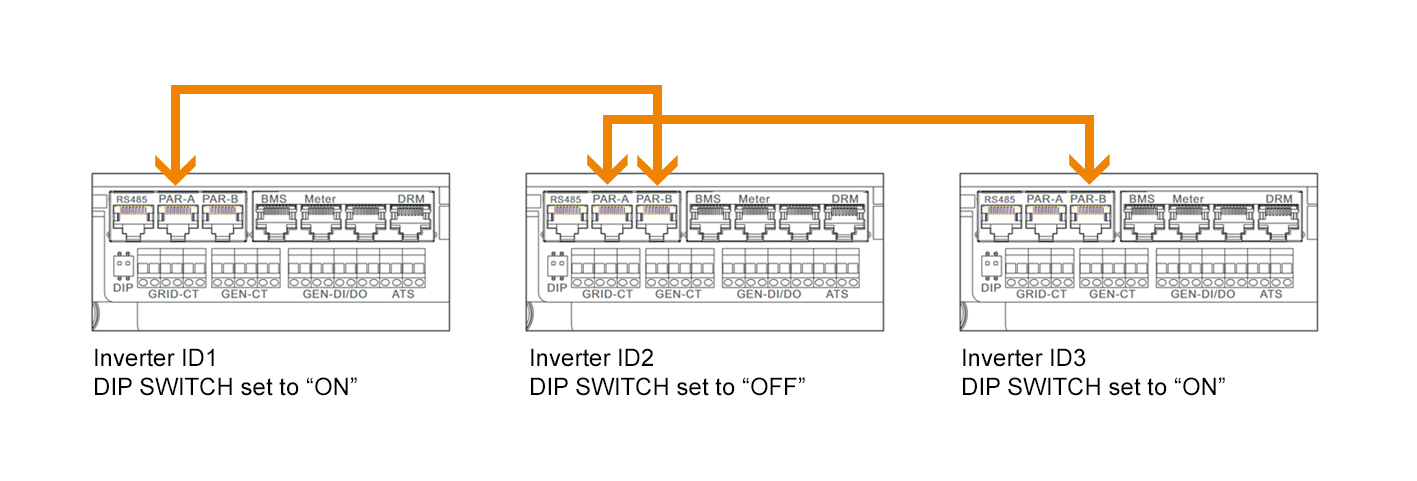
S6-EH3P(12-20)K-H Paralleling
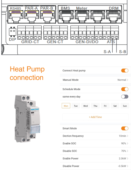
Heat Pump Connection:

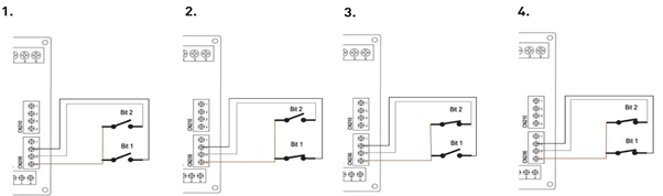
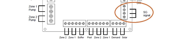
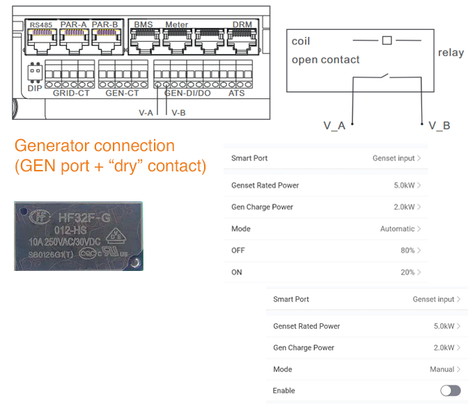
Generator Connection:
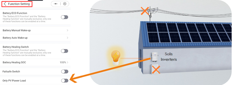
PV-only load – reduces initial customer investment costs

S6-EH3P(12-20)K-H Implementation Diagrams
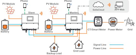
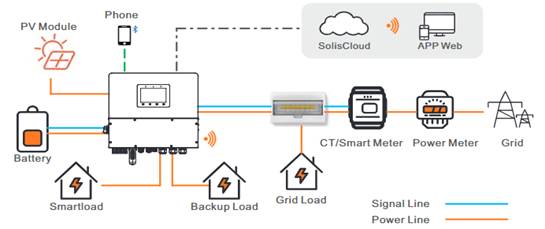
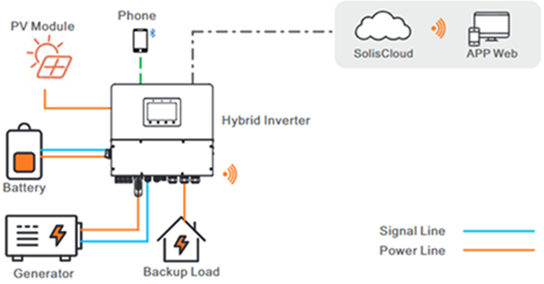
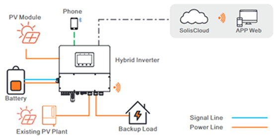
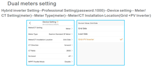
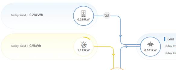
S6-EH3P(12-20)K-H – Dual Meter Settings
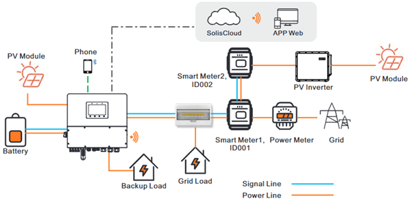

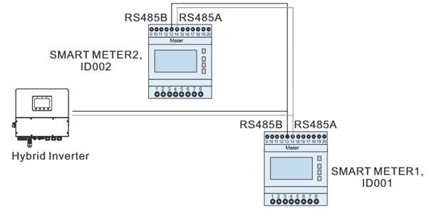



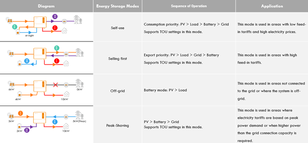
Energy Storage Modes
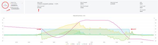
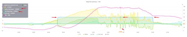
Application of the Energy Storage “Selling First” Mode

S6-EH3P(30-60)K-H(21A) - Solis S6 Advanced Hybrid Inverter
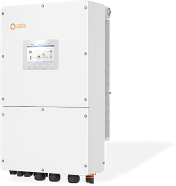
4 MPPT - 8 strings up to 21 A and up to 100 kW usable PV power
168A / 84+84A - Maximum charge/discharge
Compatible with leading global battery brands
Pre-assembled battery cables, energy meter, and data logger included in the box
Remote Monitoring - For clear understanding and analysis
Automatic UPS switching - <10ms
Parallel system - On-grid or off-grid, Max. 6 (10) inverters in parallel
160% overload capacity for 2s - Temporary overload
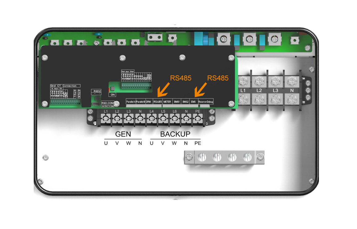
S6-EH3P(30-60)K-H - Communications Ports
S6-EH3P(80-125)K10-NV-YD-H
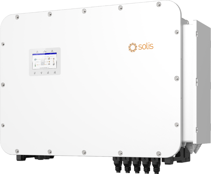
10 MPPT / 20 strings - 21 A per string input current
200A/100+100A - Maximum charge/discharge
Compatible with leading global battery brands
Supports unbalanced output up to 41.6 kW per phase
Supports 2× PV input oversizing - High DC/AC ratios
Automatic UPS switching - <10ms
Parallel system - On-grid or off-grid, Max. 6 inverters in parallel
200% overload capacity for 10s - Temporary overload

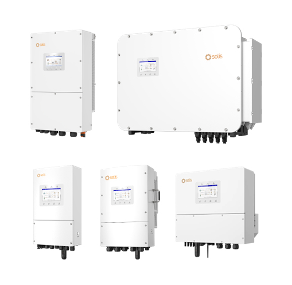
Solis S6 Hybrid solution - Smart Port Settings
1. Smart Port Functions
Scenarios & Use Cases
What Is the Smart Port on Solis S6-EH Hybrid Inverters?
- Solis S6-EH series hybrid inverters feature an integrated Backup Port for supplying critical loads during a grid outage.
- During a grid outage, loads connected to the Backup Port can be supplied by energy from the battery and/or PV system.
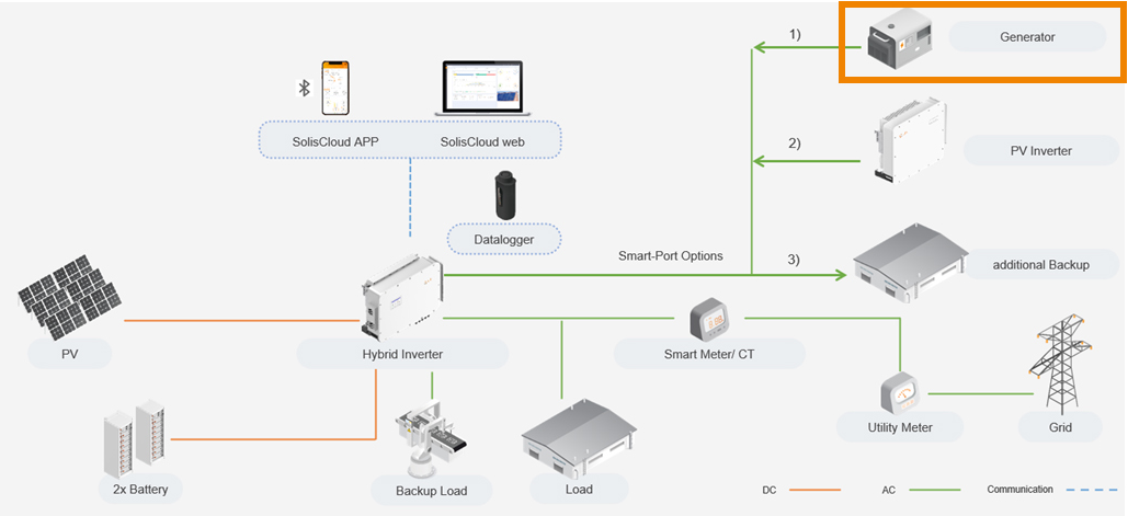
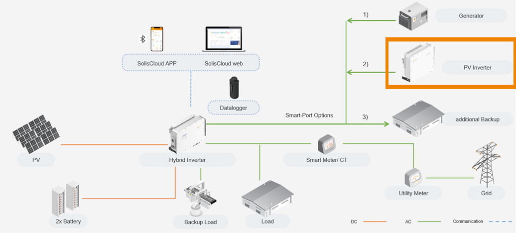
- The Smart Port is an additional AC port that supports two application scenarios:
- Generator as a secondary power source
- PV inverter as a secondary power source
- The Smart Port is available on S6-EH models equipped with this feature.
- Updating the hybrid inverter to the latest firmware version is recommended before using the Smart Port.
Operating Logic of Solis Hybrid Inverters with Smart Port
- During a grid outage: The Solis hybrid inverter supplies the backup loads using available energy from the battery and PV system. The available backup duration depends on the battery state of charge, load demand, and system configuration.
- Generator operation: The generator can be used as a secondary power source only when the system is operating in off-grid mode.
- Generator activation: As the battery state of charge (SOC) decreases and reaches the configured minimum SOC, the hybrid inverter activates the generator through the Smart Port. The generator then supplies energy to the backup loads and recharges the battery.
- Generator shutdown: Once the battery SOC reaches the configured target SOC, the hybrid inverter switches off the generator.
- AC-coupled PV inverter: An AC-coupled PV inverter can be used in both on-grid and off-grid modes. It can supply energy to the loads and, where supported by the system configuration, contribute to battery charging.
- Smart Port as a second Backup Port: When configured as a second Backup Port, the Smart Port can supply additional loads in both on-grid and off-grid operation, subject to the applicable system configuration and operating limits.
- The Smart Port is available on S6-EH models equipped with this feature.
- Updating the hybrid inverter to the latest firmware version is recommended before using the Smart Port.
2. Generator on smart port (Please note that PTO-driven generators are not supported)
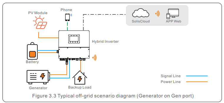
Working Mode & Diagram
Generator Operating Mode on Solis S6-EH Hybrid Inverters
- The hybrid inverter synchronizes with the generator and operates in grid-following mode when the AC grid is unavailable.
- The hybrid inverter activates the generator when the configured SOC_on threshold in the Smart Port settings is reached.
- During an AC grid outage, the generator supplies power to the backup loads through the Smart Port.
- If the generator produces more power than the backup loads require, the surplus energy can be used to charge the battery.
- The hybrid inverter deactivates the generator when the configured SOC_off threshold is reached.
- When the AC grid is unavailable, the hybrid inverter cannot synchronize with or follow the AC grid. Instead, it synchronizes with the generator frequency when the generator is operating.
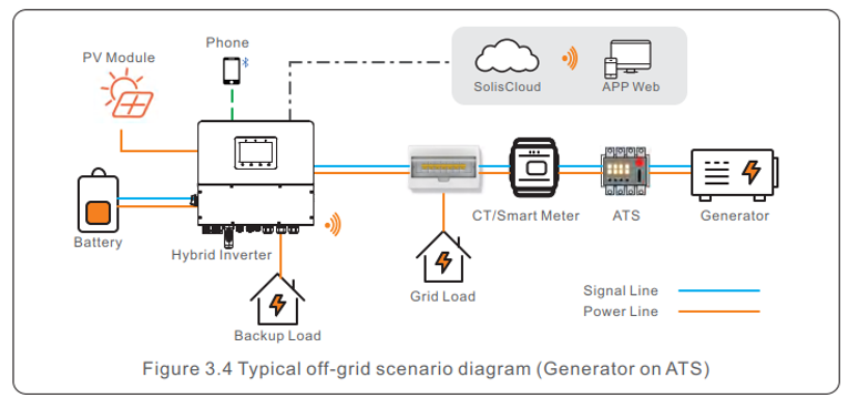
Generator Types for Off-Grid Operation
The following generator configurations can be used in off-grid applications, subject to system compatibility:
- Generator with automatic start/stop: The generator is controlled via the dry contact on the Smart Port.
- Generator with manual start/stop: The generator is manually started and stopped and does not require external communication with the inverter.
- Generator with permanent power supply: A generator can provide a permanent power source in systems equipped with an AC grid and an automatic transfer switch (ATS), subject to the applicable system configuration.
Generator Design Rules for S6-EH Hybrid Inverters
- Three-phase compatibility: Only three-phase generators should be connected to the Smart Port of three-phase hybrid inverters.
- Generator power sizing: The maximum generator input power at the Smart Port should be equal to or slightly higher than the hybrid inverter’s rated nominal power.
- Example: For the S6-EH3P50K-H, the maximum recommended generator input power at the Smart Port is 60 kW.
- Generator efficiency: Generator sizing should also take into account the generator’s operating efficiency. Most generators achieve their optimal efficiency at approximately 80% of rated load.
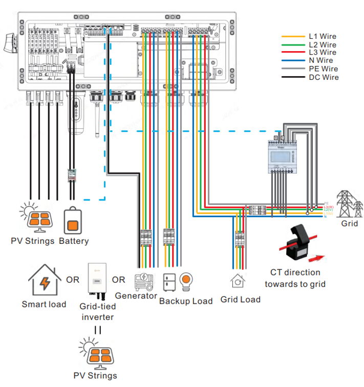
Connection wiring in S6-EH3P(12-20)K-H

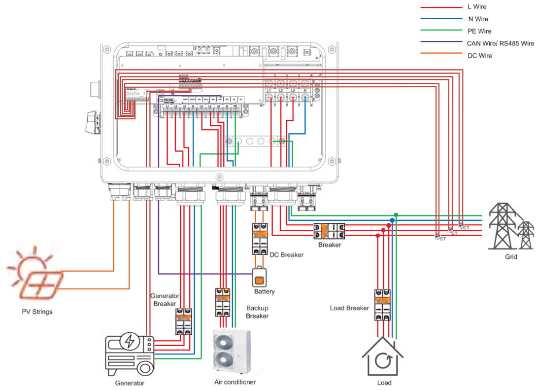
S6-EH3P(29.9-60)K-H
NOTE: Generator size: S6-EH50K-H supports range greater than 20K
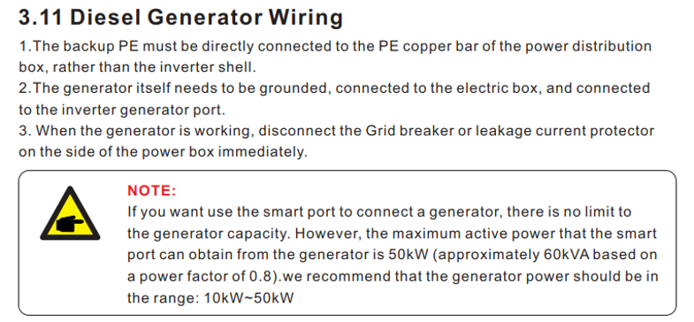
System with One Generator Supplying Backup Loads
- Follow the applicable design rules for each hybrid inverter and refer to the corresponding inverter installation manual.
- Connect the generator:
- Connect the generator AC output to the Smart Port – GEN terminals.
- Install an appropriately rated circuit breaker between each hybrid inverter and the generator to provide protection.
- Connect the backup loads:
- Connect the critical loads to the Backup Port.
- Install an appropriately rated circuit breaker between each hybrid inverter and the connected loads to provide protection.
Connection on S6-EH3P(29.9-60)K-H
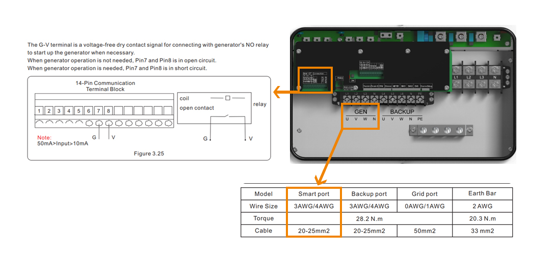
Installation Procedure for S6-EH3P(29.9–60)K-H
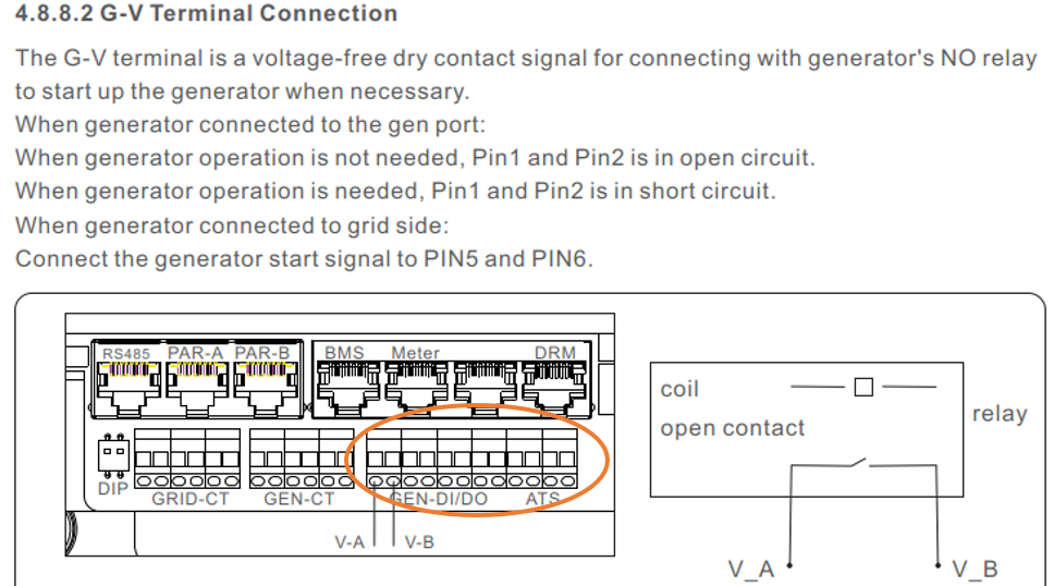
- Connect the generator: Connect the generator AC output cables to the GEN terminals on the Smart Port.
- Connect the generator start/stop control: For the generator’s automatic start/stop function, use pins 7 (G) and 8 (V) on the 14-pin communication terminal block.
- Configure the system: Complete the required settings in SolisCloud.
Parallel System
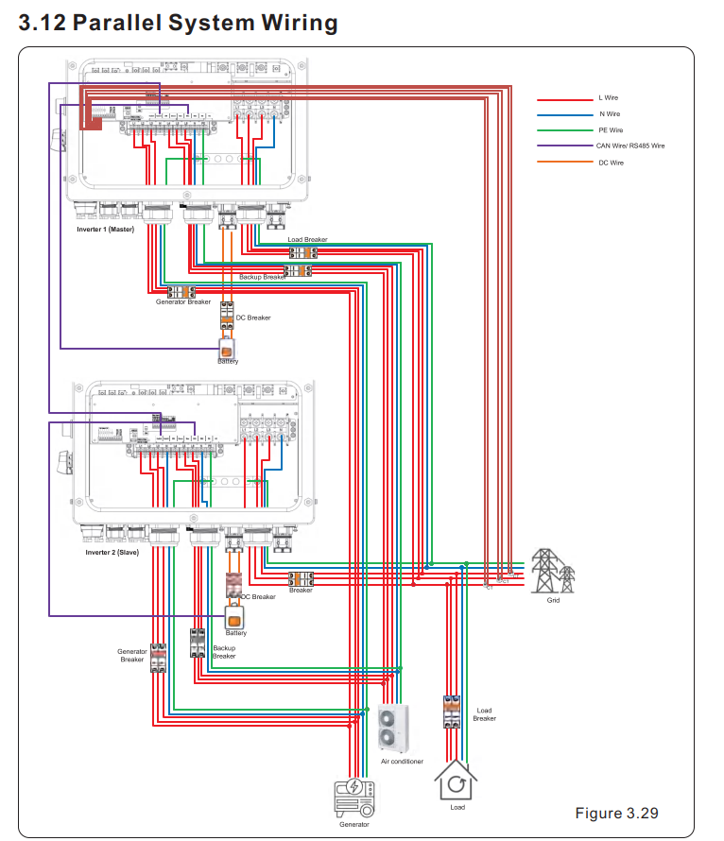
Special Case – Parallel System with One Generator Supplying All Backup Loads
- Compatible hybrid inverters: Only hybrid inverters of the same model can be connected in parallel (e.g., 2 × 50 kW, not 50 kW + 30 kW).
- Generator connection: For parallel systems using a single generator, connecting the diesel generator through an Automatic Transfer Switch (ATS) is recommended, subject to the system configuration.
- Generator sizing: The generator AC output power should be equal to or slightly higher than the combined rated AC power of all parallel hybrid inverters.
Example: For 2 × 50 kW hybrid inverters, a 100 kW generator can be used. - Connect the generator to the Smart Ports:
- Connect the GEN terminals of all hybrid inverters to the generator.
- Install an appropriately rated circuit breaker between each hybrid inverter and the generator for protection.
- Connect the Backup Ports:
- Connect the Backup Ports of all hybrid inverters to a common backup bus supplying the backup loads.
- Install appropriately rated circuit breakers between the inverters and the backup/load circuits for protection.
- Parallel configuration: Configure the hybrid inverters as a parallel system using the Master/Slave operating logic.
- Generator start/stop control: Connect the generator's automatic start/stop control to the 14-pin communication terminal of the Master hybrid inverter.
- SolisCloud configuration: Complete the required generator and parallel-system settings in SolisCloud on the Master hybrid inverter, as described in the following sections.
Setup for Smart Port - Generator
SolisCloud Desktop version:
Navigate to Smart Port and activate Genset input
- Gen rated power (AC) = rated output power of generator in Watts
- Mode: Automatic = with communication signal to start and stop
- Mode: Manual = without automatically start and stop
- SOC_on in range of 1% till 95%
- SOC_off in range of 35% till 100%


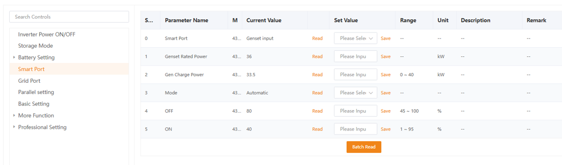

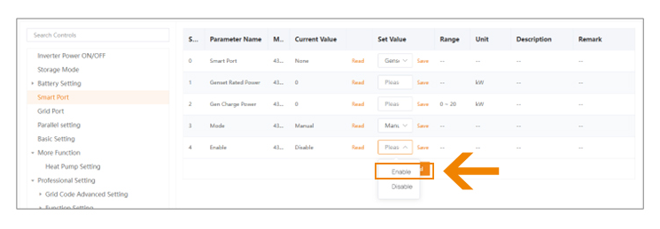
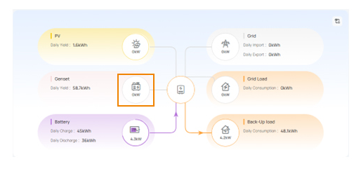
SolisCloud Overview
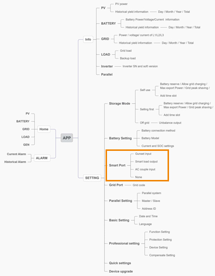
SolisCloud mobile APP:
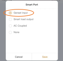
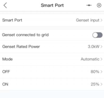
Navigate to Smart Port → Genset Input and configure the following parameters:
- Gen Rated Power: Enter the rated AC output power of the generator in watts (W).
- Mode:
- Automatic: The hybrid inverter controls the generator start/stop function through the communication signal.
- Manual: The generator is started and stopped manually and does not use the inverter's automatic start/stop signal.
- SOC_on: Set the battery state of charge (SOC) threshold at which the generator starts. The configurable range is 1% to 95%.
- SOC_off: Set the battery SOC threshold at which the generator stops. The configurable range is 35% to 100%.


3. AC coupled PV Inverters on smart port
Working Mode & Diagram
Generator Operating Mode on Solis S6-EH Hybrid Inverters
- The hybrid inverter synchronizes with the generator and operates in grid-following
Working Mode of AC-Coupled PV Inverter on Solis S6-EH Hybrid Inverters
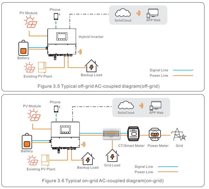
- PV inverter compatibility: The S6-EH hybrid inverter supports the connection of both Solis grid-tied PV inverters and compatible third-party grid-tied PV inverters.
- AC-coupled operation: The AC-coupled PV inverter synchronizes with the hybrid inverter. During off-grid operation, the hybrid inverter operates in grid-forming mode and establishes the AC voltage and frequency for the AC-coupled PV inverter. AC coupling can be used in both on-grid and off-grid operation.
- PV inverter grid-code settings: The AC-coupled PV inverter must be configured with the same applicable grid code as the hybrid inverter. It must also support the required frequency-response functions, including over-frequency power reduction and under-frequency power increase, where required by the system configuration.
On-Grid Operation
During on-grid operation:
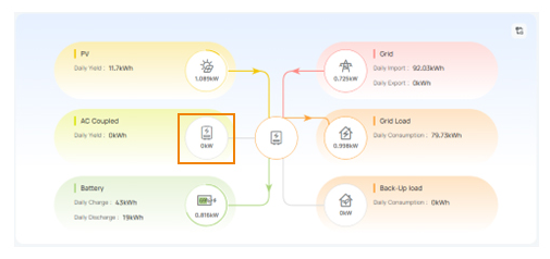
- The AC-coupled PV inverter supplies energy to the loads connected to the hybrid inverter's AC system, including the Grid Port and Backup Port, subject to the system configuration.
- Surplus PV energy can be used to charge the battery.
- If PV generation exceeds the local load and the permitted battery charging power, surplus energy may be exported to the public grid, subject to the applicable export configuration and grid requirements.
- Because the output of an AC-coupled PV inverter cannot necessarily be directly controlled by the hybrid inverter, the hybrid inverter may need to reduce its own PV generation to maintain the required power balance.
Off-Grid Operation
During off-grid operation:
- The hybrid inverter operates in grid-forming mode and establishes the AC grid for the AC-coupled PV inverter.
- Energy generated by the AC-coupled PV inverter can supply the backup loads and charge the battery, subject to the configured system limits and battery SOC.
- The hybrid inverter manages the available energy according to the configured operating logic and battery SOC.
- When PV generation exceeds the instantaneous load demand and permitted battery charging power, the AC-coupled PV inverter must reduce its output through the applicable frequency-control functions.
Power Management
- The hybrid inverter can reduce its own PV output when required to maintain the system power balance.
- The hybrid inverter's AC output remains limited by its rated AC power. Additional available PV energy cannot be used to increase the hybrid inverter's AC output beyond its rated power.
- The AC-coupled PV inverter may continue to generate power according to the available PV energy and its control limits. Therefore, appropriate frequency-response and power-reduction functions are required to prevent excess generation during off-grid operation.
- The actual power available for battery charging depends on the battery charging limits, inverter configuration, load demand, and available PV generation.
Design Rules for AC-Coupled PV Inverters on S6-EH Hybrid Inverters
- Three-phase compatibility: Only three-phase grid-tied PV inverters may be connected to the Smart Port of three-phase S6-EH hybrid inverters.
- PV inverter power rating: The rated AC output power of the AC-coupled PV inverter must be equal to or lower than the rated AC power of the S6-EH hybrid inverter.
- Example: For an S6-EH3P50K-H, the AC-coupled PV inverter connected to the Smart Port must have a rated AC output power of ≤ 50 kW.
Setup for Smart Port - AC Coupled
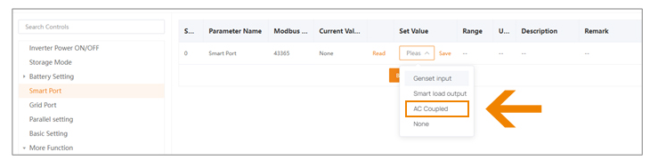
SolisCloud Desktop version:
Navigate to Smart Port and activate AC Coupled.
- Hybrid inverter: Operates in grid-forming mode; the AC-coupled PV inverter follows the hybrid inverter.
- Max Frequency (Hz): Frequency control of the AC-coupled PV inverter.
- At the configured maximum frequency, the AC-coupled PV inverter can be derated down to zero output, as the hybrid inverter cannot directly control its power output.
- Export Power & SOC: Used for off-grid operation.
- The Smart Port relay switches ON/OFF when the configured battery SOC limits are reached.
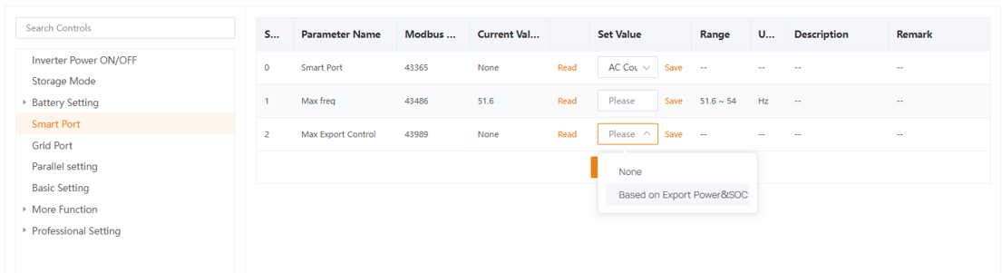
SolisCloud Overview
SolisCloud mobile APP:
Navigate to Smart Port → Genset Input and configure the following parameters:
Setup with SolisCloud Mobile App
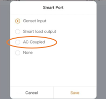
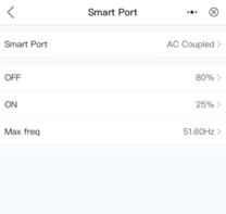
During the Quick Installation process, the app prompts for Smart Port settings in Point 3.
Navigate to Genset Input and configure:
- AC Coupled Max. Frequency
- Battery SOC limits for when the Smart Port is used as a power source.


C&I
SolisStorage C&I Energy Storage System
PrimePower Series
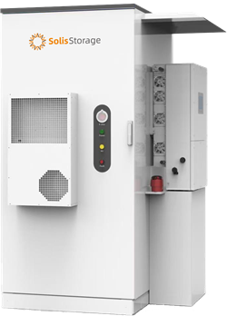
S1-109EC3P50K04-NV-YD-H
4 Unique Advantages
1: Long-Term Performance
- High-quality CATL 306 battery cells
- Extended cycle life of more than 10,000 cycles
- High cell consistency for stable, reliable long-term operation
2: Comprehensive Safety Protection
- Multi-layer protection from the individual cell level to the complete battery cabinet
- 12-level fire safety protection
- 24-hour active insulation/leakage detection
- Comprehensive battery pack temperature monitoring
3: Multiple Application Scenarios
- Supports multiple operating modes.
- Easily adaptable to 13 application scenarios.
4: Easy Maintenance
- Patented battery pack with IP67 protection, natural cooling, and a fanless design
- Separate mounting structure for the hybrid inverter, helping to reduce the risk of heat accumulation
- Maintenance-free combustible-gas sensor with a service life of up to 10 years
- Supports remote OTA updates via SolisCloud
Easy Maintenance
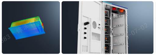
Patented IP67-rated battery pack with natural cooling and a fanless design.
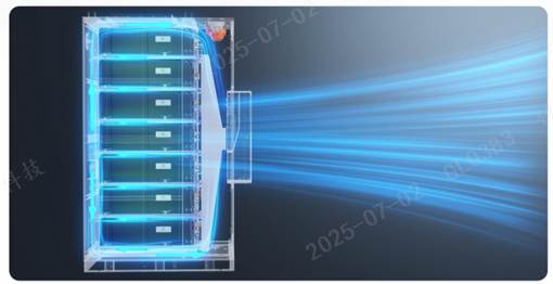
High IP protection ratings: Battery module IP67, cabinet IP55, and inverter IP66
High corrosion resistance: C4 corrosion protection; C5 available as an optional configuration
No coolant required: No periodic coolant filling or replacement is required
Patented natural-cooling module design: The battery module features a heat-equalization plate and does not require a fan for module-level cooling. A built-in cabinet air-conditioning system provides uniform temperature control throughout the battery cabinet.
Expandable Capabilities
AC-side parallel connection: Supports up to 6 units in parallel, enabling the total system inverter capacity to be expanded up to 300 kW.
DC-side parallel connection: Supports up to 6 battery cabinets in parallel, enabling the total battery capacity to be expanded up to 654 kWh.
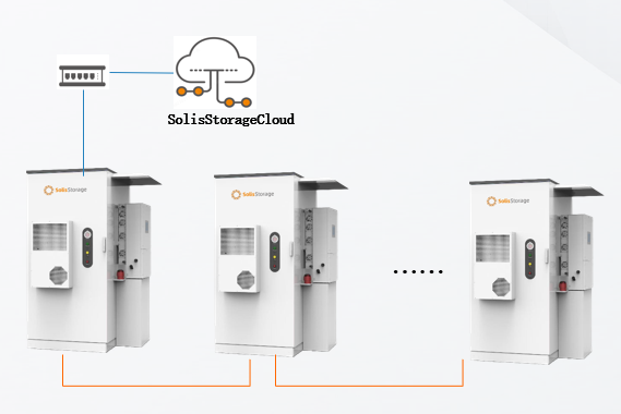
Up to 6 units in parallel (AC side)
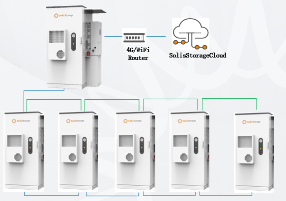
Up to 6 battery cabinets in parallel to a single 50/125 kW inverter.

SolisStorage

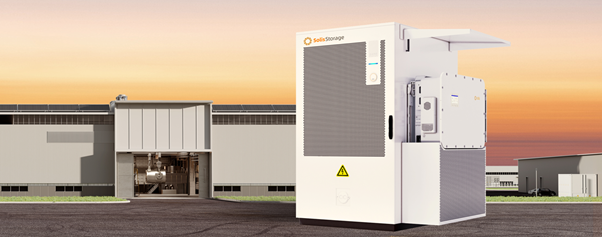
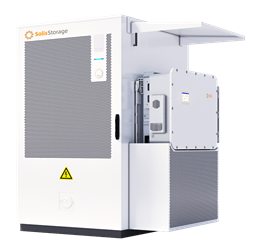
EverCore-261kWh-125kW-NV | EverCore-(100-120)kWh-(50-60)kW-NV

100/120kWh System
50K/60K inverter + 100/120 kWh battery
- 100kWh , 314Ah, 1P20S, 5 Packs (IP20), 0.5C
- 120kWh , 314Ah, 1P20S, 6 Packs (IP20), 0.5C
Suitable for
380/400V Grid:
- Inverter: 30K/40K/50K/60K

125K inverter + 261 kWh battery
261kWh , 314Ah, 1P20S, 13 Packs (IP20), 0.5C
Suitable for
380/400V Grid:
- Inverter :80K/100K/125K
8 Unique Advantages
- High-capacity 314 Ah premium cells deliver high performance, reliability, and long service life.
- Dual-level air-cooling design: Independent cooling at both the battery module and system levels provides uniform and efficient thermal management.
- 15-level protection system provides comprehensive protection from the individual cell level through the module and complete system.
- Thermal isolation between the inverter and battery cells reduces heat transfer, helping to improve system stability and extend component service life.
- Supports up to 2× the nominal PV input power, maximizing solar energy utilization.
- Supports PV input currents of up to 21 A per string, providing compatibility with high-power PV modules.
- 160% overload capability for up to 200 ms in off-grid mode enables reliable startup of high-power loads.
- SolisCloud: Provides intelligent remote monitoring and management, AI-based optimization, and real-time diagnostics through a single platform.
5 Competitive Advantages
- Fast on-grid/off-grid transfer: Switches between on-grid and off-grid modes in less than 10 ms, helping to minimize power interruptions. ①
- Flexible grid and generator integration: Supports flexible operation in weak-grid and generator (genset) hybrid systems, helping to reduce system investment costs.
- Scalable system capacity: Supports system expansion up to 1.25 MW / 15.66 MWh, providing flexibility to meet growing energy demands. ②
- AI and VPP readiness: Supports AI integration and Virtual Power Plant (VPP) applications, enabling dynamic tariff optimization, potential electricity cost savings, and additional revenue opportunities.
- Remote monitoring and OTA updates: Supports remote system monitoring and over-the-air (OTA) updates via the SolisStorage Cloud platform.
① When multiple inverters operate in parallel, switching time does not exceed 20 ms.
② When more than 6 inverters are connected in parallel, the use of a Solis power distribution cabinet is
recommended.
Flexible system expansion – up to 1.25 MW / 15.66 MWh, adapted to growing energy demands.
Note: When more than 6 inverters are connected in parallel, the use of a Solis power distribution cabinet is recommended.
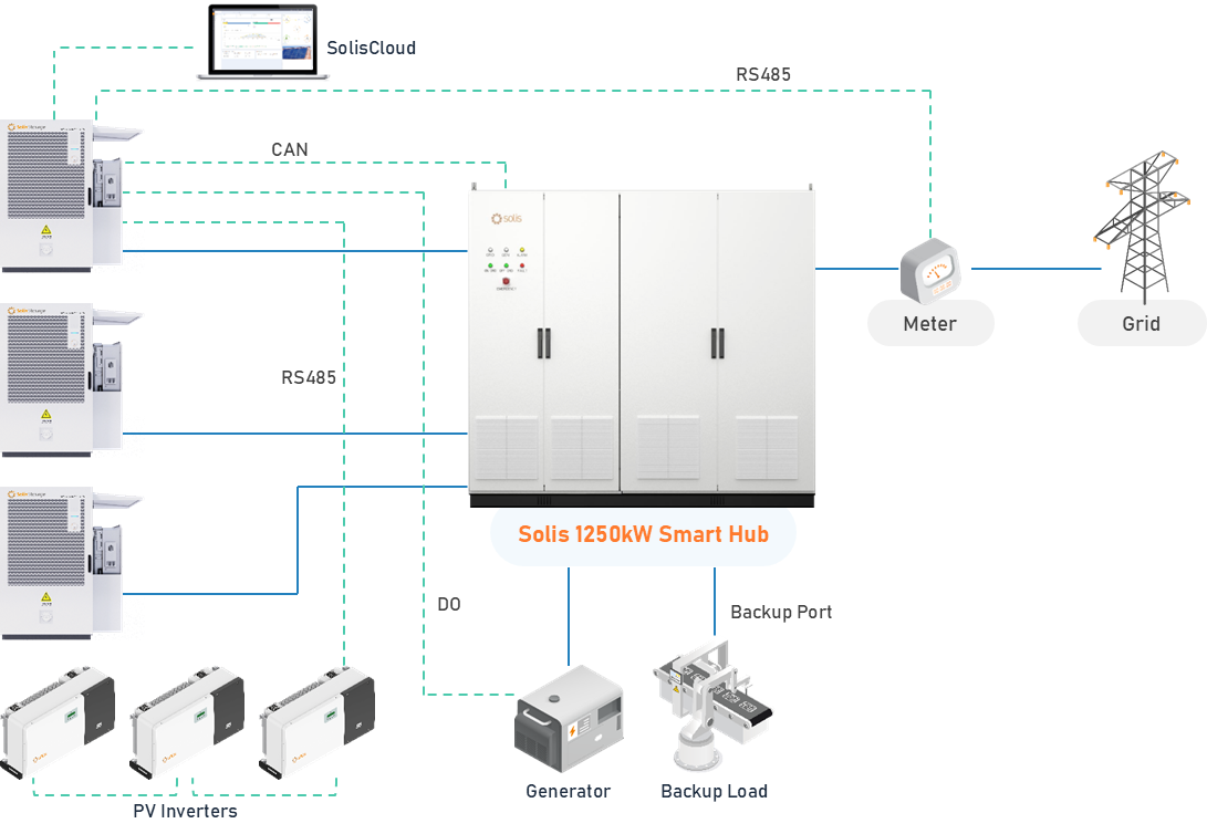
Applicable condition:
When more than 6 hybrid inverters are connected in parallel, the Solis C&I Smart Hub is recommended for system integration. It enables efficient connection and management of all system components through a centralized electrical cabinet, helping to reduce the need for additional accessories and associated costs.
- Fast system transfer: The system can achieve a switching time of less than 20 ms, helping to minimize power interruptions in C&I applications.
Solis Storage Batteries
IntelliHouse
5-16kWh Wall/Floor-Mounted Low-Voltage Energy Storage System
IP66
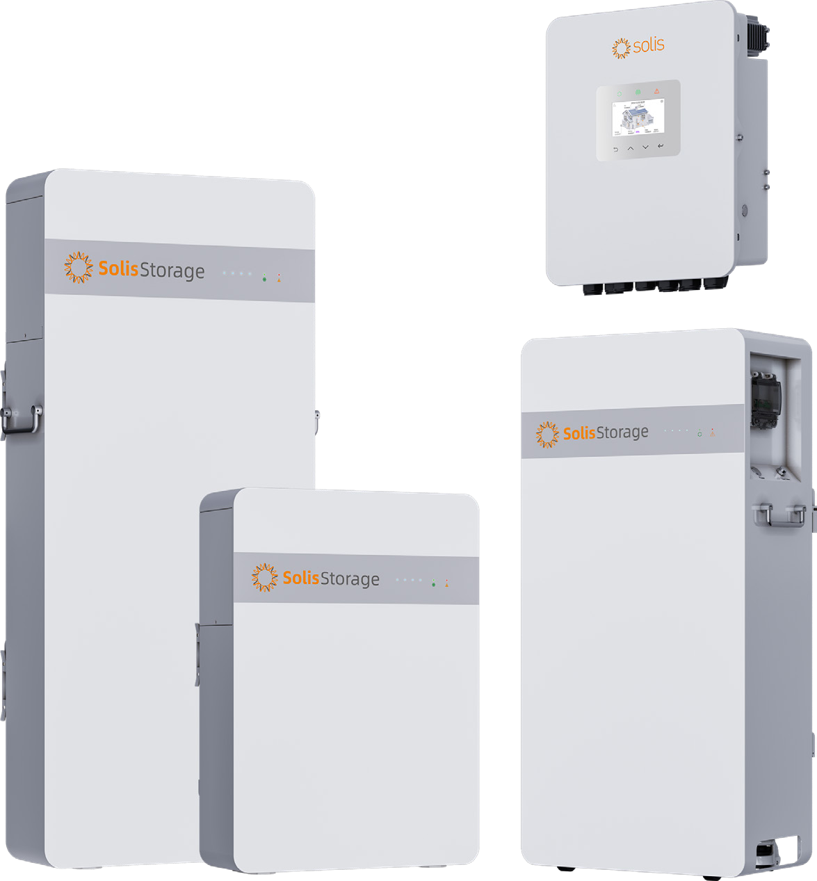
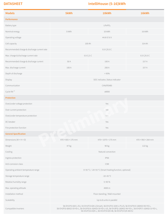

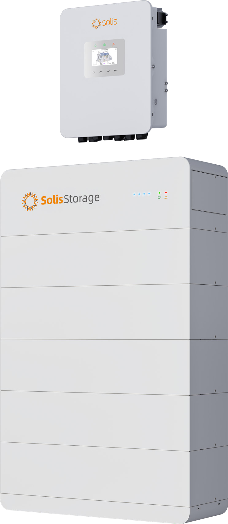
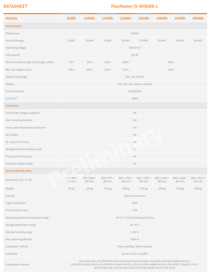
FlexHome-L
5-40kWh Stackable Low-Voltage Energy Storage System
IP66
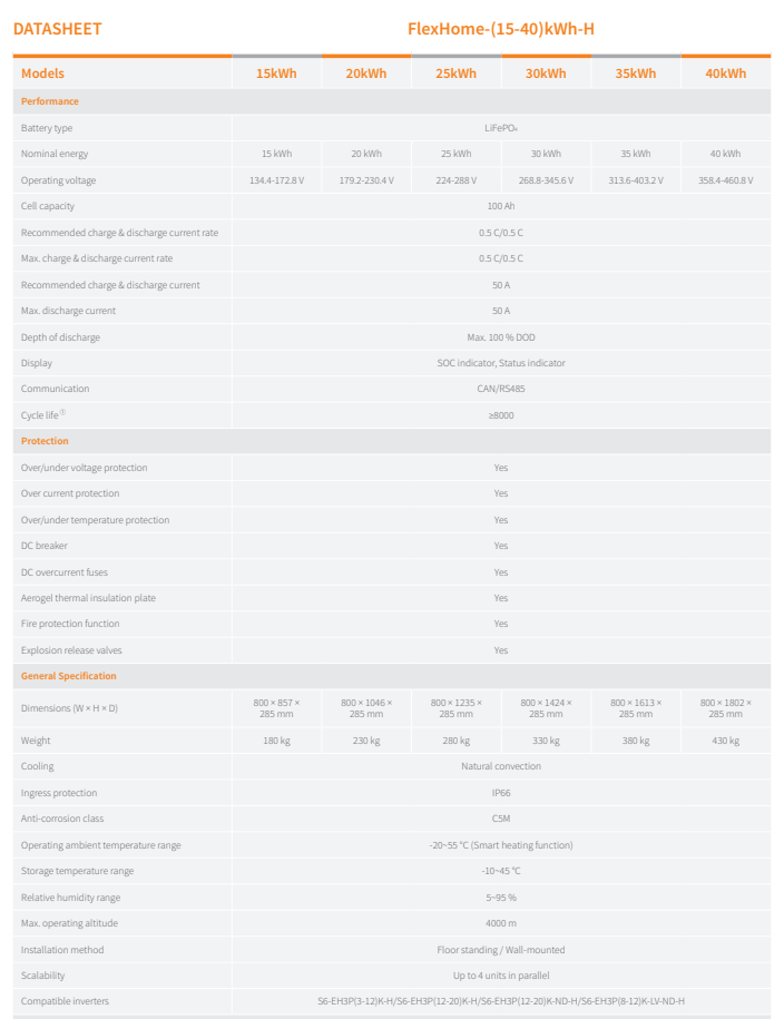
FlexHome-H 15-40kWh Stackable High-Voltage Energy Storage System
IP66

SOLIS EMS – Smart Energy Management
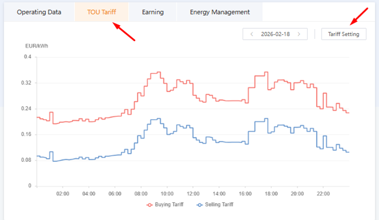
Smart Energy Management is an advanced Solis feature designed to support dynamic electricity pricing scenarios. It combines local electricity price data with intelligent algorithms to optimize the charging and discharging of energy storage systems, helping to improve energy efficiency and reduce electricity costs.
Smart Energy Management consists of two functional modules:
1. Time-of-Use (TOU) Tariffs
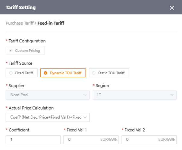
TOU electricity price data is integrated from third-party platforms, including Octopus, Nord Pool, and Flatpeak. Users can view applicable electricity prices through the platform, while the price data also serves as an input for the intelligent energy management algorithms.
Supported regions:
Finland, Norway, Sweden, Denmark, Latvia, Lithuania, Estonia, Germany, France, Austria, Belgium, the United Kingdom, the Netherlands, and Poland.
2. Energy Management
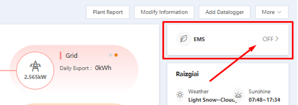
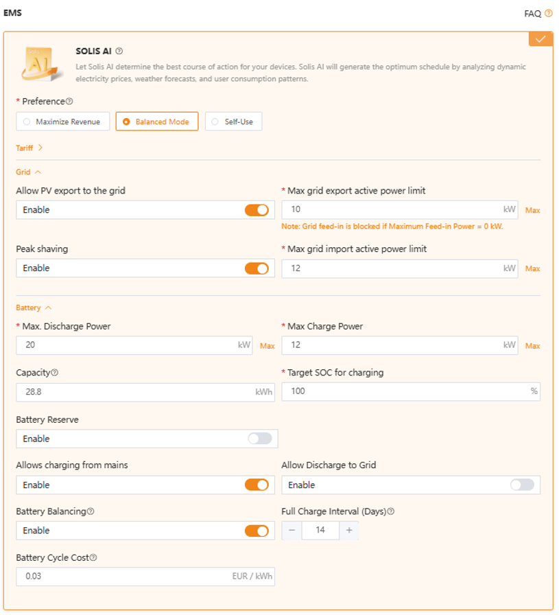
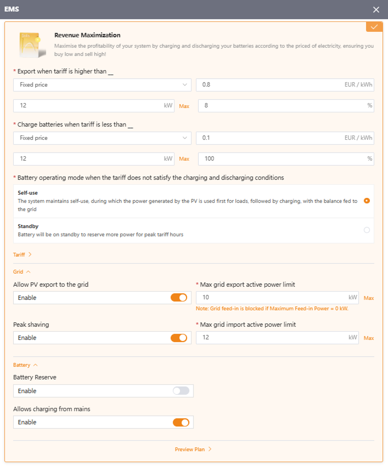
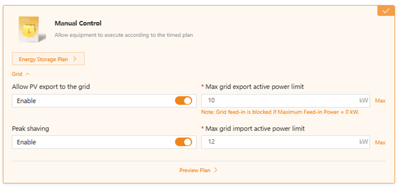
Users can select different operating modes based on TOU tariffs, electricity generation, and consumption patterns. These modes enable flexible management of the energy storage system and help optimize energy costs.
Available modes:
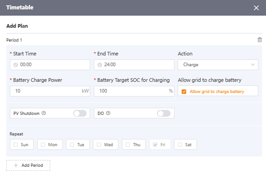
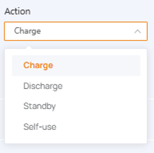
- Scheduled Time Plan
- Peak-Valley Arbitrage
- Solis AI
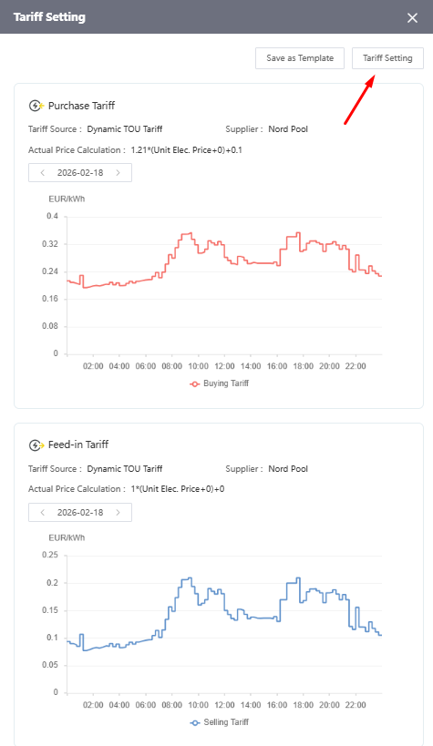
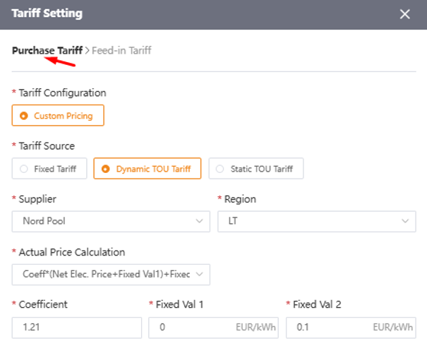
1. Tariff settings



1. EMS function settings

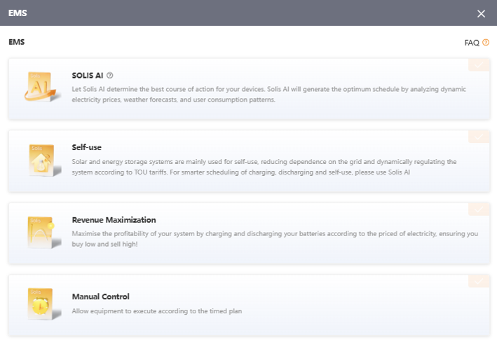

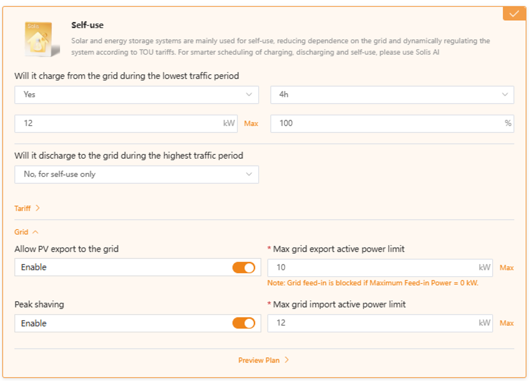

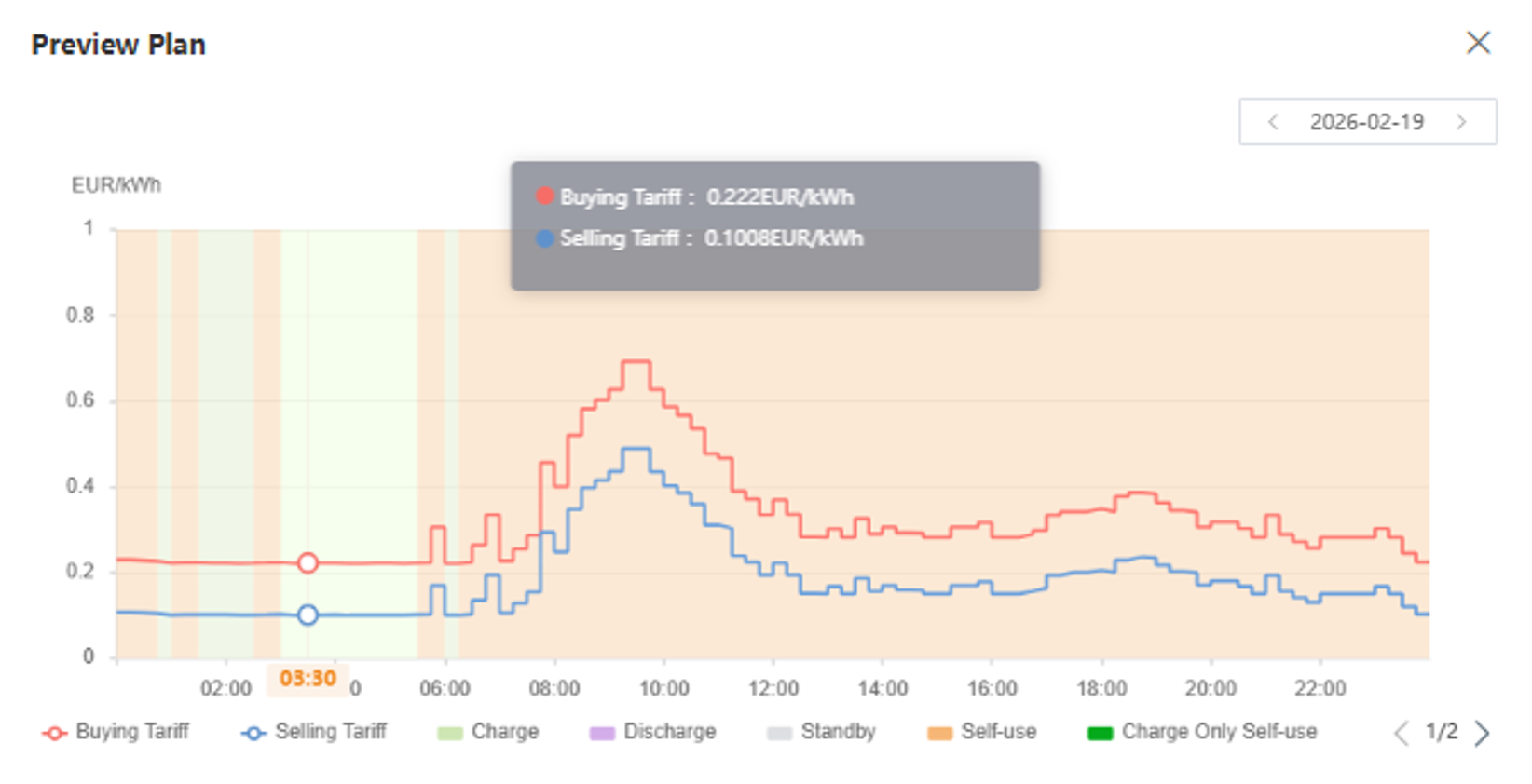
1. EMS Functions
Solis AI
Revenue Maximization
Manual Control


RMA Process
To ensure a smooth and efficient RMA replacement process, please follow the steps below:
- Do not remove or replace the inverter without prior authorization. Do not attempt repairs or advanced fault diagnosis unless instructed by Solis Technical Support.
For installations located far from the service center or support team, we recommend completing all applicable basic measurements before arranging an RMA replacement. The required measurements may include:
a. PV input: PV+ to PV−, PV+ to PE, and PV− to PE
b. AC input: L1–L2, L2–L3, and L3–L1
c. Inverter installation: Photos showing how and where the inverter is installed
d. Inverter serial number: A clear photo of the inverter SN label
- Measurement documentation: Please provide clear photos showing the multimeter display, probe connection points, and the surrounding equipment and wiring at the measurement location. Ensure that all measurement points are clearly identifiable.
- Submit a support ticket: Register a support ticket with all relevant information and measurement results, then wait for further instructions from Solis Technical Support.